⛰️ Tempest terrain 1: geometry clipmaps
Tempest doesn't have a terrain system yet, so I spent my christmas holiday on creating one. I had collected some references and had some visions in mind of what it could look like: A weighted mix between City Skylines 2, Diablo 4, RDD2, and Unreal's Terrain system. I also want Procedural content generation to be integrated deeply into the terrain system. Most importantly I like to have it behave differently based on weather conditions, without diving too deep into erosion. I found this talk from Aaron Aikman: H2O in H3LL: The Various Forms of Water in 'Diablo IV', Which inspired me to do something about the non-existing terrain system in tempest.
Let's define some goals
I want terrain that:
- covers a big area
- keeps detail near the camera
- stays roughly the same cost while moving
- doesn’t require one huge mesh
- is easy to extend (snow, vegetation, procedural content)
- looks great in first person and from top down.
Why not just one mesh?
A single terrain mesh doesn’t scale well:
- vertex count grows with world size
- updates get expensive (rebuilds, stitching, streaming)
- we end up spending detail where we don’t need it
- hiding LOD changes gets messy if we split into chunks
Even if we chunk the world, we still fight two problems:
- too much geometry far away
- seams and pops where chunk LODs meet
Clipmaps
Geometry clipmaps solve this by drawing nested grids around the camera:
- the inner grid is high detail
- outer rings are lower detail but cover more area
- total vertex count stays roughly constant
- the terrain "moves" by shifting a grid origin, not by rebuilding meshes
This is the classic reference and what I wanted to recreate:
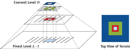
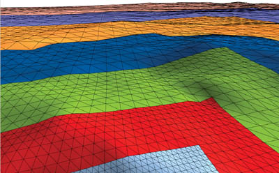
This is also commonly in used water rendering. You'd generate the clipmaps and then run FFT + gestner waves. I'd like to try this later in the terrain series, and perhaps add a whirlpool like in the movie the Pirates of the Carribean.
How we build the rings
Instead of generating terrain geometry every frame, we prebuild a small library of mesh pieces:
TILE(main interior quads)EDGE_A,EDGE_B(long strips)FILL_A,FILL_B(patches that plug gaps on LOD1+)TRIM_A,TRIM_B(LOD0-specific strips to meet LOD1 cleanly)
These meshes are generated once on the CPU (grid vertices + indices) and uploaded once into a static GPU pool.
The key point is that geometry cost doesn’t scale with world size. It scales with the clipmap resolution we choose, and we can pick that resolution based on whether we’re aiming at a top-down camera or a first-person camera.
Offsets and the ring layout
Each LOD ring is drawn by placing those same pieces at fixed offsets. LOD0 is a little special (more pieces) so the handoff into LOD1 behaves.
The render loop is basically:
- for each LOD:
- compute the scale (meters-per-vertex)
- compute an origin that follows the camera, snapped to the grid
- draw the same set of pieces at fixed offsets
Snapping and keeping things consistent
If the clipmap origin follows the camera smoothly, the surface appears to "swim" under movement. It also causes problems for anything that uses frame history later (TAA, reprojection, temporal effects).
So each LOD origin snaps to its grid step size. Coarser LOD means a bigger snap step.
- LOD0: small snap step
- LODN: higher LODs grow with power of two: snap step =
2^(N+1) * vertexSpacing
We also track alignment against the next LOD so we can pick the correct edge pieces.
This makes sampling and shading behave more predictably as the camera moves.
Here's a simplified version of the snap logic:
float snappedX = floorf(camX / VertexSpacing)* VertexSpacing;
float snappedZ = floorf(camZ / VertexSpacing)* VertexSpacing;

for(u32 lod =0; lod < Lods;++lod)
{
  float snapStep =(float)(1u<<(lod +1))* VertexSpacing;
  float nextSnapStep =(float)(1u<<(lod +2))* VertexSpacing;

  float posX =roundf(snappedX / snapStep)* snapStep;
  float posZ =roundf(snappedZ / snapStep)* snapStep;

  float nextX =roundf(snappedX / nextSnapStep)* nextSnapStep;
  float nextZ =roundf(snappedZ / nextSnapStep)* nextSnapStep;

  LodPos[lod]=V3(posX,0, posZ);

  // Used to pick which edge strip to use (alignment vs next LOD)
  int testX =ClampInt((int)roundf((posX - nextX)/ snapStep)+1,0,2);
  int testZ =ClampInt((int)roundf((posZ - nextZ)/ snapStep)+1,0,2);
  LodTestX[lod]= testX;
  LodTestZ[lod]= testZ;
}
Seams between rings
Different LOD densities meet at ring boundaries. If we do nothing, cracks and flicker show up.
Right now we’re using a simple approach:
- skirts at ring borders
- a small overlap between rings
It’s not the final solution, but it keeps the surface connected while we build out the rest.
I also have a debug toggle that draws ring edges, which makes this stuff way easier to iterate on.
Vertex shader: sampling height without shimmer
Each clipmap vertex starts as a grid point in local tile space. In the vertex shader we:
- convert local grid coords to world XZ using the LOD scale + translation
- find which terrain region/tile owns that world position (via a region table)
- sample height from a texture array layer
- choose a height mip level based on how coarse the current LOD is
The important part is the mip selection. Coarse rings shouldn’t sample the highest-frequency height detail, because it causes visible vertex-height shimmer under movement.
float SampleHeightWS(vec2 worldXZ,float lodScale)
{
  vec2 uv;
  float layer;
  vec2 invSize;
  FindRegion(worldXZ, uv, layer, invSize);

  // baseCell = world meters per height texel for this specific region
  float sizeX =1.0/ max(invSize.x,1e-8);
  float sizeZ =1.0/ max(invSize.y,1e-8);
  float baseCell = max(sizeX * uCB.Params1.x, sizeZ * uCB.Params1.y);

  float mipCount = HeightMipCount();
  float lod = clamp(log2(max(lodScale / max(baseCell,1e-6),1.0)),0.0, mipCount -1.0);

  float h = textureLod(uHeightTex, vec3(uv, layer), lod).r;
  return h * uCB.Params0.y + uCB.Params0.z;
}
To support that, we build a CPU box-filter mip chain per height tile and upload all mip levels into the height texture array. It’s basic, but it reduces the shimmer a lot and makes the distant rings behave better.
TAA
Still figuring this out.
We have a geomorph path in the shader that blends vertices toward the next LOD grid in an outer “morph zone”, but the tricky part is motion vectors and reprojection. When vertices morph, “previous position” needs careful handling or temporal history gets confused.
For now we take the safe route: if a vertex is in the morph zone, we avoid providing misleading velocity to TAA.
Texturing + materials (splat + arrays)
Each terrain region stores:
- height (R32F)
- splat weights (RGBA8)
- wetness (R8)
All of these are texture arrays, indexed by a per-tile layer value stored in the region table.
Each region also carries four material IDs (RGBA → four global material indices). In the fragment shader we:
- read splat weights
- map them to material textures (albedo/normal/ORM arrays)
- height-blend weights
- apply slope-based cliff triplanar
- add macro noise + a detail normal
- apply wetness (darkening, roughness changes, and a light coat spec)
There’s a lot going on, but the intent is straightforward: materials should not shift around as the clipmap rings snap and follow the camera. This post focuses on the geometry side; the next post will go deeper on height and slope blending.
What we have so far
- nested grid layout (clipmap rings)
- camera-following origin
- snapped per-LOD origins
- ring debug visualization
- height mip chains
- texture-array region lookup (height/splat/wetness)
- simple seam strategy (skirts + overlap)
Future work
- smoother ring transition blending (better geomorph + shading continuity)
- better normals across boundaries
- faster region lookup (spatial acceleration instead of a linear scan)